Synchronization
The Résonique concept has been simulated. A set of two differential equations coupled by magnetic forces is enough to mathematically demonstrate the possibility of having the gear train’s rotational speed synchronized with a sustained resonator. Both of these equations are based on Newton’s second law linking the acceleration of a body with his mass m and the net force it is subject to.
Equation (1) determines the gear train’s angular motion. The first term, on the left side of the equation represents the rotor’s angular acceleration and the gear train’s total inertia. The second term is the torque of the barrel, modelled as decreasing linearly. The third term is the friction torque, which is proportional to the rotational speed, due to viscous interaction. Finally, the last term is the magnetic torque, which depends on the location of the oscillator and the angular location of the rotor.
Equation (2) determines the oscillator’s motion. The first term, on the left side represents the oscillator’s acceleration and equivalent mass. The second term is the elastic force. The third term is the friction forces, which are proportional to the speed, due to viscous interaction. Finally, the last term is the magnetic force, which depends on the location of the oscillator and the angular location of the rotor.
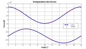
Both these equations are coupled by magnetic forces, that depend on the rotor and the magnet geometry. They are modelled by the finite element method. The concept was tested by a numerical analysis with finite difference method. The simulation demonstrated that a phase synchronisation between oscillator and rotor can be achieved depending on the values chosen as parameters.
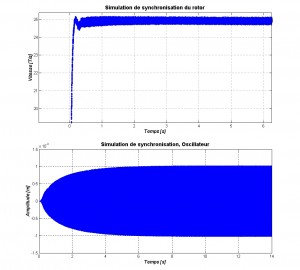
After a transient phase, the rotor’s speed and oscillator’s amplitude become stationary. The oscillator’s amplitude compensates for the barrel’s decreasing torque, so that synchronisation can occurs over a relatively large energy variation. Random perturbations were added to check synchronisation in more realistic conditions. The simulations accomplished, were sufficient to confirm our hypothesis, and to finely model finely working prototypes.
Differential equations
Magnetic force
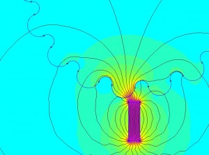
Magnetic forces were simulated using the finite elements method. This helped determining the size of the rotor and the permanent magnets with regard to the primary aim: An energy transmission curve with a sinusoidal form when the rotor is turning at constant speed. The secondary aim was to have a strongly localized magnetic field in order not to disturb the rest of the mechanism.
 |
 |
Resonator
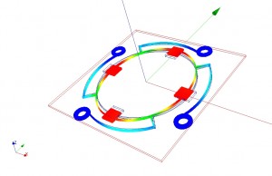
Resonators were also simulated using the finite elements method, adding several analytical models in order to evaluate damping, mostly due to thermal flow, aerodynamics frictions, energy absorption by the binding plate and interfering vibrations. Simulation allowed testing various vibration modes in order to determine optimal frequencies and power levels. Simulation also allowed testing of different materials and to select those offering the best Q factor.


